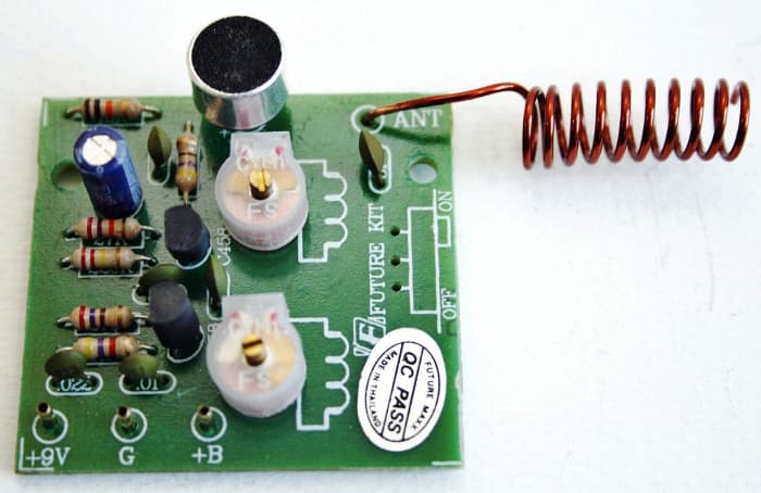

A field strength meter shows the strength of the actual field being radiated from your antenna. Therefore, a field strength meter is used to test the output of the FM transmitter. This is certainly the case on the emitter of the second transistor, where the leads of a multimeter will draw off so much energy that the stage will stop working. The voltages around the oscillator stage cannot be measured with an ordinary multimeter as the leads of a millimeter will act an antenna when the circuit is operating and kill the operation of the circuit. For about 30-50 meters range, a 15cm antenna is sufficient but if you need to get a most extreme range you can utilize a half-wave antenna.Ī telescopically extendable antenna Testing the FM Transmitter: Its length ought to be given or take 1/4 the FM wavelength review that duplicating frequency and wavelength equivalents the speed of light. In that capacity, you can utilize a telescopically extendable antenna for example ones discovered in radios. A 22 measure copper wire is suitable for the antenna. This is the place where the electronic FM signal is changed over to electromagnetic waves, which are transmitted into the atmosphere. The last/final stage of any FM transmitter is the FM antenna. This will give the circuit more dependability and more output. The FM transmitter circuit is enhanced by including this buffer or output stage so that the oscillator is not driving antenna. The signal handled by the oscillator stage is not exceptionally capable so we pass it to an amplifying stage called an output stage to increase the amplitude. This stage amplifies the output RF signal. The transistor and its components encompassing the tuned circuit essentially keep the tuned circuit working at its resonant frequency. Each transmitter circuit needs an oscillator part to create the RF waves. In this stage, the amplified audio input signal is adjusted for transmission. This stage is said to be AC coupled as it has a capacitor on both the input and output so the DC voltages of the different stages don’t impact the voltage on the stage. Just an exceptionally self-biasing emitter stage is used for the sound enhancer. In this stage, the signal is amplified moreover 70-100 times and is currently huge enough to be infused into the RF stage. The output waveform at the micro-phone is passed through a coupling capacitor to an emitter stage. The capacitor disconnects the microphone from the base voltage of the transistor and permits just AC signs to pass through. It conveys these to the oscillator stage. The pre-amplifier is a self-biasing emitter fit for amplifying the signals got by the micro-phone. This capacitor is intended to divide the DC voltage on the receiver from the voltage concerning the transistor. A 22n capacitor on the output of the micro-phone couples the sign to the first sound pre-amplifier stage. Alternately assuming that you need to utilize altered resistor as a part of the spot of the variable resistor and would prefer not to change the sound quality then a 5K resistor might be utilized. A variable resistor at a micro-phone is utilized to alter the audio quality of the amplifier and modify the variable resistor to get the best quality.


 0 kommentar(er)
